其他相关文章:
- 关于MPLS:
- 在MPLS环境下,每次转发数据包所查找的表都分别是什么?
- 【实验】使用MPLS解决BGP路由黑洞的问题
- 如果您想查看更多关于MPLS的内容请在搜索框中搜索:“MPLS”。
- 关于MPLS L3VPN:
- MPLS L3VPN为什么要使用两层MPLS标签?
- 如果您想查看更多关于MPLS L3VPN的内容请在搜索框中搜索:“MPLS L3VPN”。
实验环境:
- 使用四台Cisco 2811路由器,IOS是目前最新的c2800nm-adventerprisek9-mz.151-4.M10.bin
- 还有两台Cisco 3750三层交换机,IOS是目前最新的c3750-ipservicesk9-mz.122-55.SE10.bin
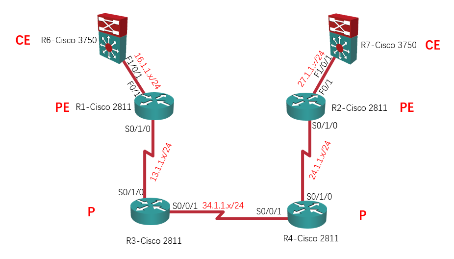
实验需求:
- 在上述拓扑中配置MPLS L3VPN;
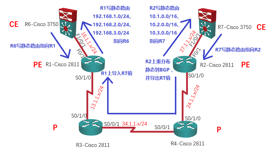
- R1和R2是PE;
- R3和R4是P;
- R6和R7是CE;
- R1上的RD值为1234:6,RT值为67:6,R2上的RD值为1234:7,RT值为67:7(正常情况下,同一家公司的RD值应该是一致的,这里之所以不一致是因为后面在这个地方要说明一些东西);
- R6有三个LAN网段:192.168.1.0/24、192.168.2.0/24和192.168.3.0/24,这三个LAN网段要通告到BGP中;
- R7有三个LAN网段:10.1.0.0/16、10.2.0.0/16和10.3.0.0/16,这三个LAN网段要通告到BGP中。
科普一下:CE是Customer Edge Router,客户边界路由器;PE是Provider Edge Router,服务提供商边界路由器;P是Provider Router,服务提供商核心路由器或服务提供商骨干路由器。
实验步骤:
注意:因为这是Ricky第一次发关于MPLS L3VPN的实验文章,所以这里我会描述得详细一点。步骤分为这几步:
- 1、配置IP地址
- 2、配置P和PE上的IGP和MPLS
- 3、配置VRF
- 4、配置MP-BGP
- 5、PE和CE之间写静态路由,同时R2上重分布静态到BGP
- 6、R2上导出RT值
- 7、R1上导入RT值
- 8、R1上重分布静态到BGP
- 9、R1上导出RT值
- 10、R2上导入RT值
千万千万,别看晕了哟~ _(:з」∠)_
1、配置IP地址:
| R1 – Cisco 2811:
int l 0 int s 0/1/0 int f 0/1 |
R2 – Cisco 2811:
int l 0 int s 0/1/0 int f 0/1 |
| R3 – Cisco 2811:
int l 0 int s 0/1/0 int s 0/0/1 |
R4 – Cisco 2811:
int l 0 int s 0/1/0 int s 0/0/1 |
| R6 – Cisco 3750:
ip routing int l 0 int f 1/0/1 |
R7 – Cisco 3750:
ip routing int l 0 int f 1/0/1 |
2、配置P和PE上的IGP和MPLS:
| R1 – Cisco 2811:
router isis 1234 int s 0/1/0 mpls ip router isis 1234 |
R2 – Cisco 2811:
router isis 1234 int s 0/1/0 mpls ip router isis 1234 |
| R3 – Cisco 2811:
router isis 1234 int s 0/1/0 int s 0/0/1 mpls ip router isis 1234 |
R4 – Cisco 2811:
router isis 1234 int s 0/1/0 int s 0/0/1 mpls ip router isis 1234 |
3、配置VRF:
| R1 – Cisco 2811:
ip vrf R6 int f 0/1 |
R2 – Cisco 2811:
ip vrf R7 int f 0/1 |
注意:如下图所示,这里将接口划到VRF下时,原先配置的IP地址将会被移除,所以需要重新配置IP地址。
R1(config-vrf)#int f 0/1
R1(config-if)#ip vrf forwarding R6
% Interface FastEthernet0/1 IPv4 disabled and address(es) removed due to
 enabling VRF R6
R1(config-if)#ip add 16.1.1.1 255.255.255.0

R2(config-vrf)#int f 0/1
R2(config-if)#ip vrf forwarding R7
% Interface FastEthernet0/1 IPv4 disabled and address(es) removed due to
 enabling VRF R7
R2(config-if)#ip add 27.1.1.2 255.255.255.0
现在我们看一下跟VRF有关的show命令,看VRF是否正常工作:
- sh ip vrf:可以查看当前路由器上配置了多少个VRF,他们的RD值分别是什么,哪些接口划入了VRF;
- sh ip vrf detail:可以查看更详细的有关于VRF的信息;
- sh ip route vrf R1:可以查看每个VRF下的RIB(路由表)。
R1#sh ip vrf
  Name                             Default RD          Interfaces
  R6                               1234:6              Fa0/1

R1#sh ip vrf detail
VRF R6 (VRF Id = 1); default RD 1234:6; default VPNID <not set>
Interfaces:
    Fa0/1
VRF Table ID = 1
  No Export VPN route-target communities
  No Import VPN route-target communities
  No import route-map
  No export route-map
  VRF label distribution protocol: not configured
  VRF label allocation mode: per-prefix

R1#sh ip route vrf R6

Routing Table: R6
Codes: L - local, C - connected, S - static, R - RIP, M - mobile, B - BGP
       D - EIGRP, EX - EIGRP external, O - OSPF, IA - OSPF inter area
       N1 - OSPF NSSA external type 1, N2 - OSPF NSSA external type 2
       E1 - OSPF external type 1, E2 - OSPF external type 2
       i - IS-IS, su - IS-IS summary, L1 - IS-IS level-1, L2 - IS-IS level-2
       ia - IS-IS inter area, * - candidate default, U - per-user static route
       o - ODR, P - periodic downloaded static route, H - NHRP, l - LISP
       + - replicated route, % - next hop override

Gateway of last resort is not set

      16.0.0.0/8 is variably subnetted, 2 subnets, 2 masks
C        16.1.1.0/24 is directly connected, FastEthernet0/1
L        16.1.1.1/32 is directly connected, FastEthernet0/1
现在R6 – Cisco 3750是可以ping到R1 – Cisco 2811的:
R6#ping 16.1.1.1

Type escape sequence to abort.
Sending 5, 100-byte ICMP Echos to 16.1.1.1, timeout is 2 seconds:
!!!!!
Success rate is 100 percent (5/5), round-trip min/avg/max = 1/4/9 ms
但是因为现在R1 – Cisco 2811的F0/1口划入到了VRF中,所以默认R1 – Cisco 2811是ping不到R6 – Cisco 3750的:
R1#ping 16.1.1.6
Type escape sequence to abort.
Sending 5, 100-byte ICMP Echos to 16.1.1.6, timeout is 2 seconds:
.....
Success rate is 0 percent (0/5)
那如何才能ping通呢?这就需要到VRF下去ping了:
R1#ping vrf R6 16.1.1.6
Type escape sequence to abort.
Sending 5, 100-byte ICMP Echos to 16.1.1.6, timeout is 2 seconds:
..!!!
Success rate is 60 percent (3/5), round-trip min/avg/max = 1/3/4 ms
4、配置MP-BGP:
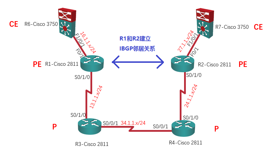
| R1 – Cisco 2811:
router bgp 1234 address-family vpnv4 |
R2 – Cisco 2811:
router bgp 1234 address-family vpnv4 |
注意:neighbor x.x.x.x send-community extended这条命令会在配置完neighbor x.x.x.x activate后自动配置,你自己是可以不用配置的。
以前我们都是用show ip bgp summary去查看IPv4 Unicast的BGP邻居关系是否建立,然而现在我们建立的是VPNv4 Unicast的BGP邻居关系,这条命令就没法查看了:
R2#show ip bgp summary
R2#
现在用这条sh bgp vpnv4 unicast all summary命令查看VPNv4 Unicast的BGP邻居关系:
R2#sh bgp vpnv4 unicast all summary
BGP router identifier 2.2.2.2, local AS number 1234
BGP table version is 1, main routing table version 1

Neighbor    V       AS MsgRcvd MsgSent   TblVer  InQ OutQ Up/Down  State/PfxRcd
1.1.1.1     4     1234      11      11        1    0    0 00:06:39        0
其实,当你运行到这一步的时候,BGP已经自动在VRF下运行了。如下图所示,sh ip protocols这条命令可以查看当前路由器下都分别运行了哪些路由协议:
R2#sh ip protocols
*** IP Routing is NSF aware ***

Routing Protocol is "isis 1234"
  Outgoing update filter list for all interfaces is not set
  Incoming update filter list for all interfaces is not set
  Redistributing: isis 1234
  Address Summarization:
    None
  Maximum path: 4
  Routing for Networks:
    Serial0/1/0
  Passive Interface(s):
    Loopback0
  Routing Information Sources:
    Gateway         Distance      Last Update
    1.1.1.1              115      00:07:46
    3.3.3.3              115      00:07:46
    4.4.4.4              115      00:07:46
  Distance: (default is 115)

Routing Protocol is "bgp 1234"
  Outgoing update filter list for all interfaces is not set
  Incoming update filter list for all interfaces is not set
  IGP synchronization is disabled
  Automatic route summarization is disabled
  Maximum path: 1
  Routing Information Sources:
    Gateway         Distance      Last Update
  Distance: external 20 internal 200 local 200
然而通过这条sh ip protocols vrf R7命令你会发现,在VRF下,子路由器里面已经运行BGP了:
R2#sh ip protocols vrf R7
*** IP Routing is NSF aware ***

Routing Protocol is "bgp 1234"
  Outgoing update filter list for all interfaces is not set
  Incoming update filter list for all interfaces is not set
  IGP synchronization is disabled
  Automatic route summarization is disabled
  Maximum path: 1
  Routing Information Sources:
    Gateway         Distance      Last Update
  Distance: external 20 internal 200 local 200
5、PE和CE之间写静态路由,同时R2上重分布静态到BGP:
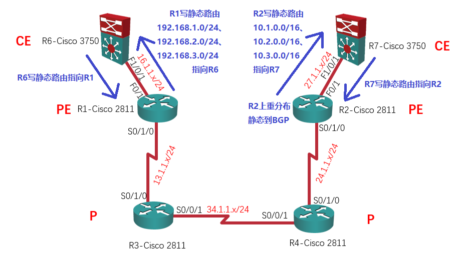
现在R6 – Cisco 3750内有三个LAN网段需要通告给R7 – Cisco 3750,他们分别是:192.168.1.0/24、192.168.2.0/24和192.168.3.0/24;
R7 – Cisco 3750内也有三个LAN网段需要通告给R6 – Cisco 3750,他们分别是:10.1.0.0/16、10.2.0.0/16和10.3.0.0/16。
为了省事儿,我们在CE和PE之间暂不运行IGP协议,而是通过静态路由的方式让PE知道CE有哪些路由。
| R6 – Cisco 3750:
ip route 0.0.0.0 0.0.0.0 f 1/0/1 16.1.1.1 |
R7 – Cisco 3750:
ip route 0.0.0.0 0.0.0.0 f 1/0/1 27.1.1.2 |
| R1 – Cisco 2811:
ip route vrf R6 192.168.1.0 255.255.255.0 f 0/1 16.1.1.6 |
R2 – Cisco 2811:
ip route vrf R7 10.1.0.0 255.255.0.0 f 0/1 27.1.1.7 |
注意:
1)如果要写的静态路由在VRF里,就要加VRF参数,比如:ip route vrf R6 192.168.1.0 255.255.255.0 f 0/1 16.1.1.6。
2)R6和R7这里写静态默认路由也是为了省事儿,如果你想写明细的静态路由可以这么写:
| R6 – Cisco 3750:
ip route 10.1.0.0 255.255.0.0 f 1/0/1 16.1.1.1 |
R7 – Cisco 3750:
ip route 192.168.1.0 255.255.255.0 f 1/0/1 27.1.1.2 |
现在,我们需要在R2 – Cisco 2811上将这些静态路由重分布进BGP,重分布后这些路由将会变成VPNv4路由,最终让这些VPNv4路由通过BGP传递到R1 – Cisco 2811上:
R2(config)#router bgp 1234
R2(config-router)#add ipv4 vrf R7
R2(config-router-af)#redistribute Static
重分布完成以后,BGP就拥有了这些VPNv4路由,通过show bgp vpnv4 un all命令我们可以查看BGP分别拥有和收到哪些VPNv4路由:
R2#show bgp vpnv4 un all
BGP table version is 4, local router ID is 2.2.2.2
Status codes: s suppressed, d damped, h history, * valid, > best, i - internal,
              r RIB-failure, S Stale, m multipath, b backup-path,
              x best-external, f RT-Filter
Origin codes: i - IGP, e - EGP, ? - incomplete

   Network          Next Hop            Metric LocPrf Weight Path
Route Distinguisher: 1234:7 (default for vrf R7)
*> 10.1.0.0/16      27.1.1.7                 0         32768 ?
*> 10.2.0.0/16      27.1.1.7                 0         32768 ?
*> 10.3.0.0/16      27.1.1.7                 0         32768 ?
这条show bgp vpnv4 un all 10.1.1.1命令可以查VPNv4路由的明细:
R2#show bgp vpnv4 un all 10.1.1.1
BGP routing table entry for 1234:7:10.1.0.0/16, version 8
Paths: (1 available, best #1, table R7)
  Advertised to update-groups:
     1
  Local
    27.1.1.7 from 0.0.0.0 (2.2.2.2)
      Origin incomplete, metric 0, localpref 100, weight 32768,valid,sourced,best
      mpls labels in/out 2003/nolabel
6、R2上导出RT值:
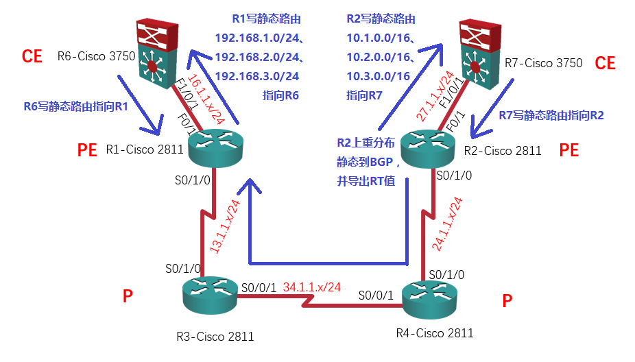
要想让这些VPNv4路由通过BGP传递到R1 – Cisco 2811上,我们还需要将这些路由导出,导出路由需要这么配置:
R2(config)#ip vrf R7
R2(config-vrf)#route-target export 67:7
然而现在你会发现R1 – Cisco 2811是收不到任何VPNv4路由的:
R1#show bgp vpnv4 un all
R1#
因为思科路由器默认在BGP上做了RT值过滤:只有本路由器配置了需要导入哪些RT值的VPNv4路由,路由器才会导入;否则,就算收到了VPNv4路由默认将会丢弃。
如果我们关闭了BGP的RT值过滤,你就会看到VPNv4路由了:
R1(config)#router bgp 1234
R1(config-router)#no bgp default route-target filter   // 关闭了BGP的RT值过滤
R1(config-router)#end

R1#clear ip bgp * so
再来看VPNv4路由,你就会看到从R2 – Cisco 2811上传递过来的VPNv4路由了:
R1#show bgp vpnv4 un all
BGP table version is 4, local router ID is 1.1.1.1
Status codes: s suppressed, d damped, h history, * valid, > best, i - internal,
              r RIB-failure, S Stale, m multipath, b backup-path,
              x best-external, f RT-Filter
Origin codes: i - IGP, e - EGP, ? - incomplete

   Network          Next Hop            Metric LocPrf Weight Path
Route Distinguisher: 1234:7
*>i10.1.0.0/16      2.2.2.2                  0    100      0 ?
*>i10.2.0.0/16      2.2.2.2                  0    100      0 ?
*>i10.3.0.0/16      2.2.2.2                  0    100      0 ?
当然,默认这条命令是可以(也是需要)开启的,否则本路由器将会收到大量的无关的VPNv4路由(特殊情况下才需要关闭,以后会讲到)。如下图所示,我们将BGP的RT值过滤打开,现在R1 – Cisco 2811就收不到R2 – Cisco 2811传来的VPNv4路由了。
R1(config)#router bgp 1234
R1(config-router)#bgp default route-target filter  // 再次开启BGP的RT值过滤功能
R1(config-router)#
R1(config-router)#do clear ip bgp * so
R1(config-router)#
R1(config-router)#do sh bgp vpnv4 un all  // 现在R1就收不到R2传来的VPNv4路由了
R1(config-router)#
那如何在开启BGP的RT值过滤功能的情况下接收R2 – Cisco 2811发来的VPNv4路由呢?那我们就需要在R1上导入相应的RT值。
7、R1上导入RT值:
因为R2 – Cisco 2811上导出的RT值是67:7,所以我们就需要在R1 – Cisco 2811上导入这个RT值:
R1(config)#ip vrf R6
R1(config-vrf)#route-target import 67:7
现在R1 – Cisco 2811收到RT值为67:7的VPNv4路由了:
R1#clear bgp vpnv4 unicast * so   // 软清一下, 让R2重新发VPNv4路由。

R1#sh bgp vpnv4 un all
BGP table version is 13, local router ID is 1.1.1.1
Status codes: s suppressed, d damped, h history, * valid, > best, i - internal,
              r RIB-failure, S Stale, m multipath, b backup-path,
              x best-external, f RT-Filter
Origin codes: i - IGP, e - EGP, ? - incomplete

   Network          Next Hop            Metric LocPrf Weight Path
Route Distinguisher: 1234:6 (default for vrf R6)
*>i10.1.0.0/16      2.2.2.2                  0    100      0 ?
*>i10.2.0.0/16      2.2.2.2                  0    100      0 ?
*>i10.3.0.0/16      2.2.2.2                  0    100      0 ?
Route Distinguisher: 1234:7
*>i10.1.0.0/16      2.2.2.2                  0    100      0 ?
*>i10.2.0.0/16      2.2.2.2                  0    100      0 ?
*>i10.3.0.0/16      2.2.2.2                  0    100      0 ?
这里你会看到两份10.1.0.0/16的路由,一份的RD值是1234:6,另一份的RD值是1234:7。
为啥会有两份呢?RD值是1234:7的那份是R2 – Cisco 2811传过来的,而RD值是1234:6的那份是R1 – Cisco 2811自己导入到VRF R6里的。(注意:正常情况下同一家公司的RD值应该是一致的,如果RD值是一致的话这里就不会出现两份VPNv4路由了。)
8、R1上重分布静态到BGP:
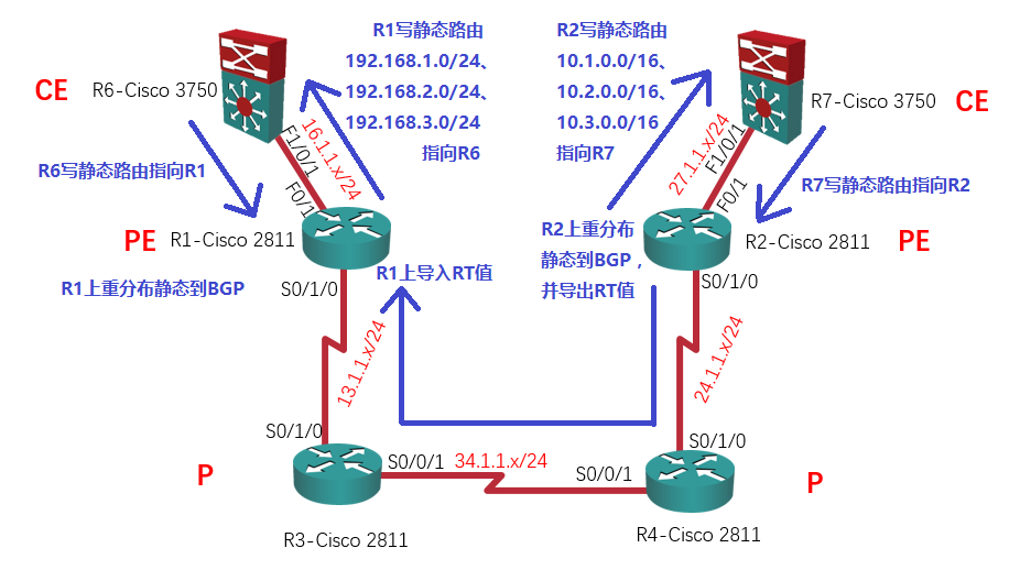
现在我们完成的是单向的VPNv4路由传递(从R2 – Cisco 2811到R1 – Cisco 2811),反过来还需要做一次:
R1(config)#router bgp 1234
R1(config-router)#add ipv4 vrf R6
R1(config-router-af)#redistribute static
9、R1上导出RT值:
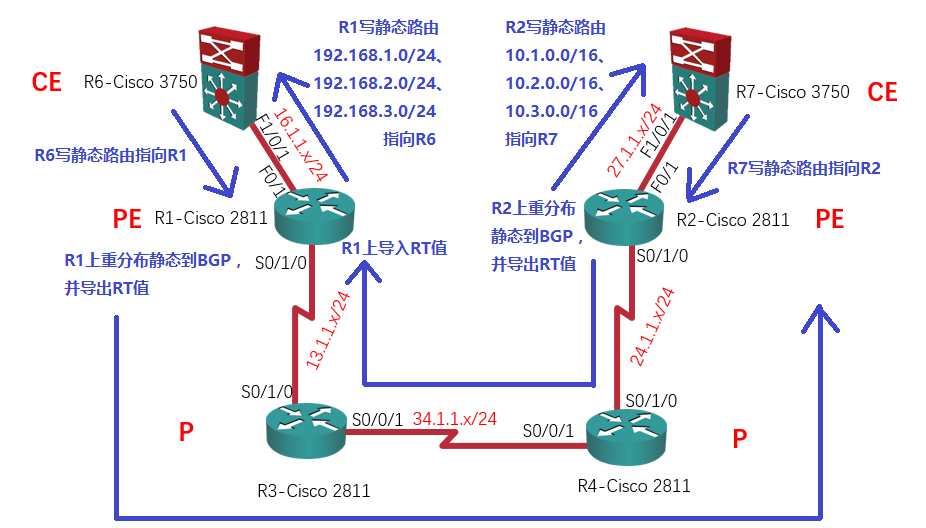
R1(config)#ip vrf R6
R1(config-vrf)#route-target export 67:6
10、R2上导入RT值:

R2(config)#ip vrf R7
R2(config-vrf)#route-target import 67:6
实验结果:
现在,R1 – Cisco 2811和R2 – Cisco 2811的VRF里都有彼此的路由了:
R1#sh ip route vrf R6

Routing Table: R6
Codes: L - local, C - connected, S - static, R - RIP, M - mobile, B - BGP
       D - EIGRP, EX - EIGRP external, O - OSPF, IA - OSPF inter area
       N1 - OSPF NSSA external type 1, N2 - OSPF NSSA external type 2
       E1 - OSPF external type 1, E2 - OSPF external type 2
       i - IS-IS, su - IS-IS summary, L1 - IS-IS level-1, L2 - IS-IS level-2
       ia - IS-IS inter area, * - candidate default, U - per-user static route
       o - ODR, P - periodic downloaded static route, H - NHRP, l - LISP
       + - replicated route, % - next hop override

Gateway of last resort is not set

      10.0.0.0/16 is subnetted, 3 subnets
B        10.1.0.0 [200/0] via 2.2.2.2, 00:12:29
B        10.2.0.0 [200/0] via 2.2.2.2, 00:12:29
B        10.3.0.0 [200/0] via 2.2.2.2, 00:12:29
      16.0.0.0/8 is variably subnetted, 2 subnets, 2 masks
C        16.1.1.0/24 is directly connected, FastEthernet0/1
L        16.1.1.1/32 is directly connected, FastEthernet0/1
S     192.168.1.0/24 [1/0] via 16.1.1.6, FastEthernet0/1
S     192.168.2.0/24 [1/0] via 16.1.1.6, FastEthernet0/1
S     192.168.3.0/24 [1/0] via 16.1.1.6, FastEthernet0/1

R2#sh ip route vrf R7

Routing Table: R7
Codes: L - local, C - connected, S - static, R - RIP, M - mobile, B - BGP
       D - EIGRP, EX - EIGRP external, O - OSPF, IA - OSPF inter area
       N1 - OSPF NSSA external type 1, N2 - OSPF NSSA external type 2
       E1 - OSPF external type 1, E2 - OSPF external type 2
       i - IS-IS, su - IS-IS summary, L1 - IS-IS level-1, L2 - IS-IS level-2
       ia - IS-IS inter area, * - candidate default, U - per-user static route
       o - ODR, P - periodic downloaded static route, H - NHRP, l - LISP
       + - replicated route, % - next hop override

Gateway of last resort is not set

      10.0.0.0/16 is subnetted, 3 subnets
S        10.1.0.0 [1/0] via 27.1.1.7, FastEthernet0/1
S        10.2.0.0 [1/0] via 27.1.1.7, FastEthernet0/1
S        10.3.0.0 [1/0] via 27.1.1.7, FastEthernet0/1
      27.0.0.0/8 is variably subnetted, 2 subnets, 2 masks
C        27.1.1.0/24 is directly connected, FastEthernet0/1
L        27.1.1.2/32 is directly connected, FastEthernet0/1
B     192.168.1.0/24 [200/0] via 1.1.1.1, 00:02:08
B     192.168.2.0/24 [200/0] via 1.1.1.1, 00:02:08
B     192.168.3.0/24 [200/0] via 1.1.1.1, 00:02:08
自然,R6 – Cisco 3750和R7 – Cisco 3750就可以互通了:
R6#p 10.1.1.1 so 192.168.1.1

Type escape sequence to abort.
Sending 5, 100-byte ICMP Echos to 10.1.1.1, timeout is 2 seconds:
Packet sent with a source address of 192.168.1.1
!!!!!
Success rate is 100 percent (5/5), round-trip min/avg/max = 1/6/9 ms

R6#p 10.2.1.1 so 192.168.2.1

Type escape sequence to abort.
Sending 5, 100-byte ICMP Echos to 10.2.1.1, timeout is 2 seconds:
Packet sent with a source address of 192.168.2.1
!!!!!
Success rate is 100 percent (5/5), round-trip min/avg/max = 1/7/9 ms

R6#p 10.3.1.1 so 192.168.3.1

Type escape sequence to abort.
Sending 5, 100-byte ICMP Echos to 10.3.1.1, timeout is 2 seconds:
Packet sent with a source address of 192.168.3.1
!!!!!
Success rate is 100 percent (5/5), round-trip min/avg/max = 1/7/9 ms
实验完成。
如果你想知道MPLS L3VPN为什么要使用两层MPLS标签,请看:《MPLS L3VPN为什么要使用两层MPLS标签?》
发表评论?